The Revit 2018 material for standing seam metal roofs has a surface pattern and an image with a bump map as a default. Most of the time this is a sufficent representation of a standing metal seam roof; the data and graphic representation is shown, and it will look fine in your construction documentation. However, when rendering, the default material for standing seam roofs does not come out so well in Revit 2018
As a result, I've put together a quick trick that will help you render views of roofs that you have already created. The trick is simple; as you have already spent time modelling all of the ridges, valleys, hips etc, it makes sense to use them rather than duplicate efforts.
- Firstly, select your modelled roof within the 3D view in Revit 2018.
- Copy the roof to the clipboard and paste it selecting the "Aligned to same place." You should now have two roofs in the same place.
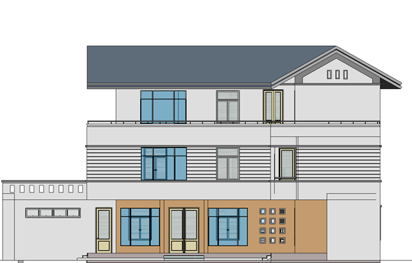
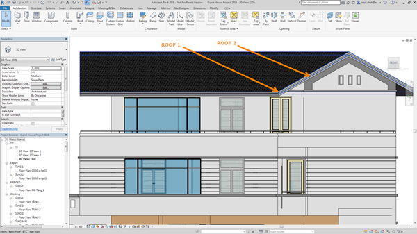
- Then orient the 3D view to an elevation view, and select one of the roofs and nudge it upwards a few spaces to show the two different roofs as below.
- Next, select the top roof and change its type to a sloped glazing (to create vertical and horizontal 3D ribs using mullions.) This can be done in the current elevation view or the previous view as below.
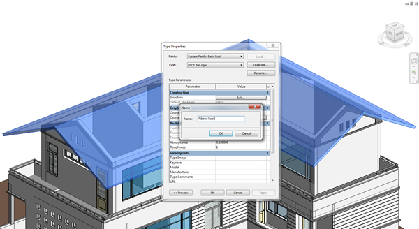
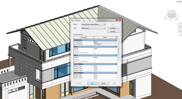
- Once you have chosen your desired view, select the sloped glazing roof and edit type. This will duplicate the roof so you will need to rename it as shown below.
- Once the roof is duplicated and renamed, you can then begin to make changes to its structure. As shown below, I have changed the curtain panel to "glazed", selected a fixed grid distance of 1000mm, and chosen the default profile of the rectangular 50 x 150mm mullion.
(Suggestion - at this point, you can customise and/or create your own profiles to be used as mullions that have the exact size and shape to it. The same applies for the horizontal and vertical grid alignments. For the purposes of demonstration, I have used the default profiles available.)
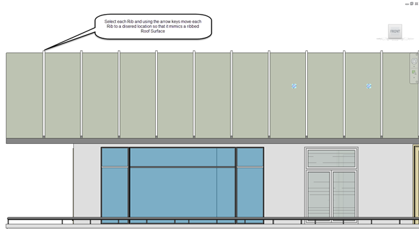
- Once done, click apply so that you can view your changes and edit as required. The ribs should then have be reflected on the roof.
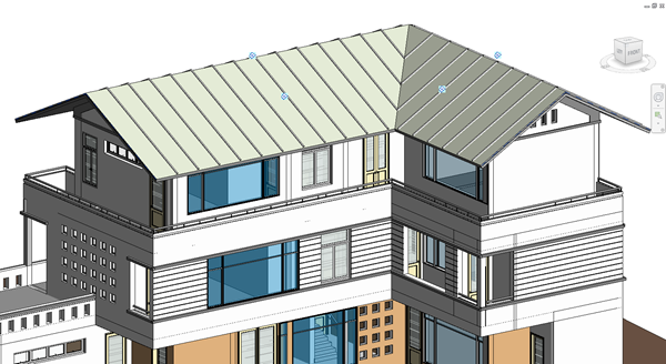
- Next, orient to any 3D elevation view using the view cube and select the glazed panel roof with the ribs as shown below. Using the arrow keys, nudge the roof back into place so that they are just appearing through the primary roof to achieve the seamed profile roof.
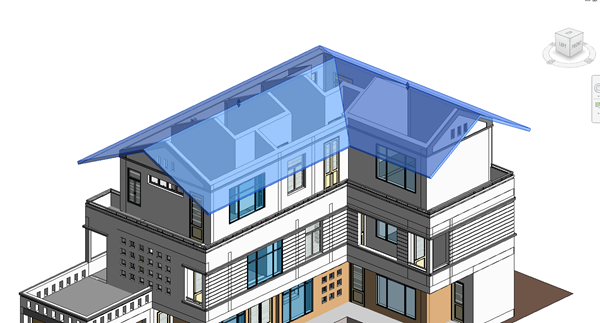
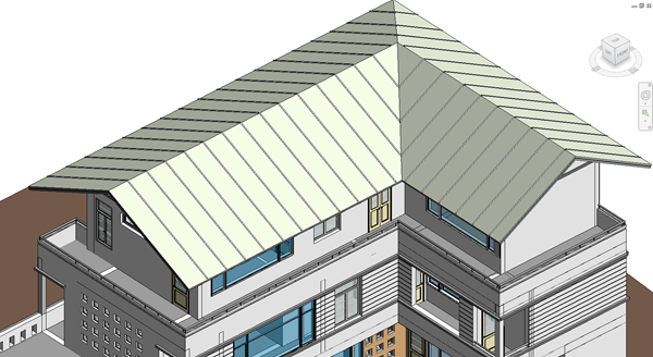
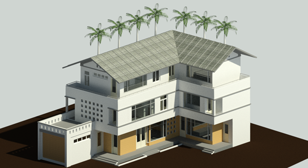
The final product should look like the figure below (based on the default isometric 3D view.)
Or shown as a rendered view.
For more information on Revit 2018, please get in touch or visit our product page here.


