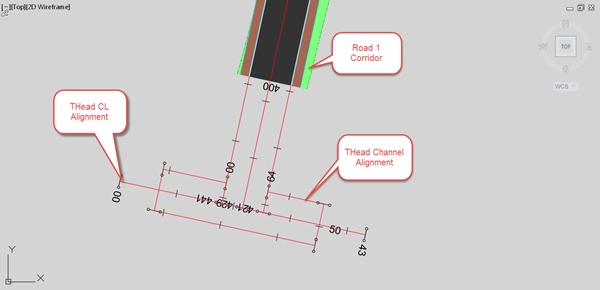
In this example, a corridor has already been created from alignment Road 1, with offset alignments on both left and right channel lines. A Corridor “Top” surface has been created for this corridor. An alignment for the shape of the turning Head, THead Channel, has been created which starts and ends at the offset alignments on Road 1. Note that the centreline alignment for the turning head, THead CL, extends beyond the channel line at either end.

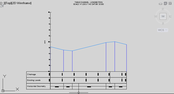
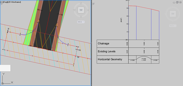
In the image above, the corridor region has been dragged back for clarity, but the next step should be performed with the Road 1 corridor (and its Top surface) ending at the turning head centreline alignment. Surface profiles are created for THead CL, using both the Existing Ground and also the Road 1 Top corridor surface. A design profile is then created which meets the Road 1 centreline levels as shown below.
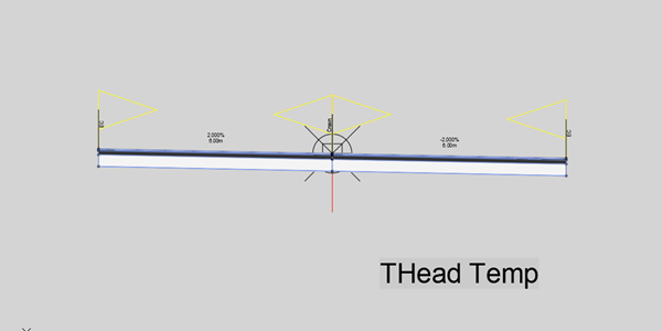
To set the levels along the channel line of the turning head in AutoCAD Civil 3D, we can use a temporary corridor. This technique is very useful when designing levels with a set cross-fall from the centreline to an odd-shaped channel line, which is often the case with modern residential road layouts.
An assembly is created for the temporary corridor, which has the required lane slopes for the turning head, and which is wider than the proposed turning head width.
This assembly is used to create a turning head temporary corridor, THeadTemp, and a “Top” surface is created on the temporary corridor. If each corridor is placed on its own separate layer, then the temporary corridor layer can be frozen to hide it in the model.
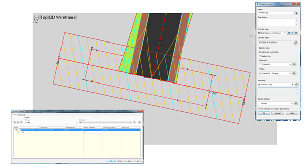
The THeadTemp corridor surface can now be used to set the levels on the turning head channel line, by creating a surface profile from THead Channel.
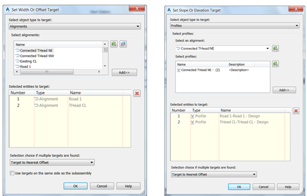
To create the junction area with the turning head, connected alignments can be used. Whilst the intersection tool might also be an option, the connected alignments are simpler to use and work well for this scenario. The first connected alignment is created by selecting the Road 1 Right Channel followed by the THead Channel alignments.
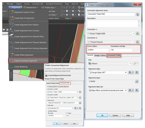
The Connected alignment for the other side of the bellmouth is created in the opposite direction, selecting first the THead Channel alignment, followed by the Road 1 Left Channel alignment. Creating the connected alignments in opposite directions allows a single assembly to be used to create the quadrants at the bellmouth. (Note that a profile must exist on both Road 1 channel line alignments for the connected alignments to also create connected profiles.)
Connected Alignments with associated profiles
The corridor modelling strategy for the Turning Head is shown in the image below. There are other alternative methods which could be used – adopt the method that uses the least amount of assemblies and corridor regions.
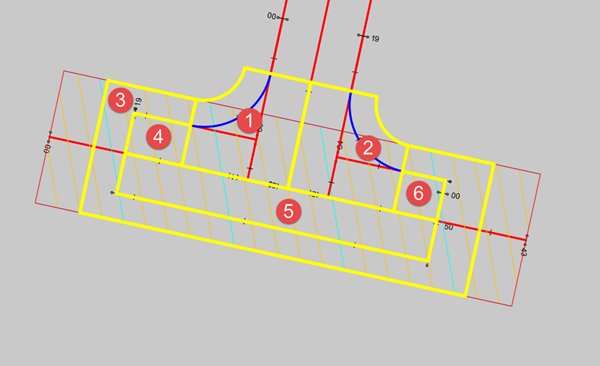
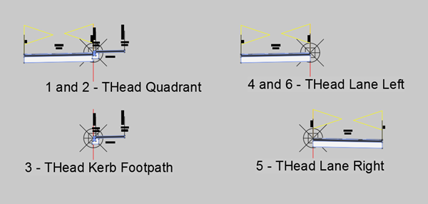
The assemblies used for the turning head are shown in the image above.
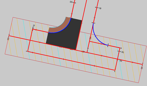
Firstly, the bellmouth quadrants 1 and 2 are created. Baselines and regions are created for each quadrant, and targets are applied to the road lane to target both Road 1 and THead CL.
The first quadrant modelled in the corridor should look like the example below:
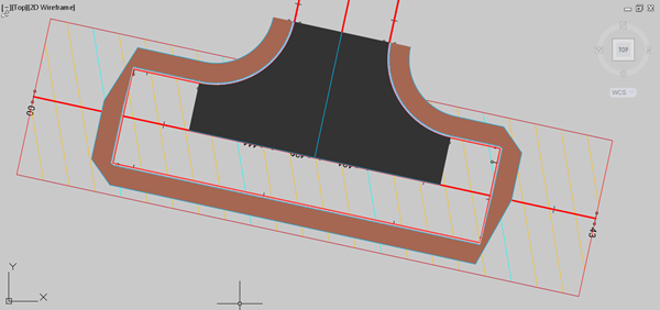
After adding the other quadrant and the kerb and footpath around the turning head, the corridor might look like the image below.
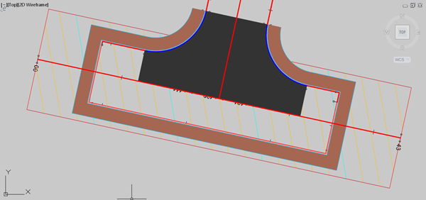
However, after rebuilding the corridor, the right-angled corners of the turning head should automatically heal to produce well-formed corners. Note that this feature only works if the assembly used for the region does not include sub-assemblies that vary in width. This is why there is no roadside grading included on this assembly. The rebuilt corridor should look like the image below.
Finally, after adding all the turning head regions to the corridor, the resulting corridor will look something like this:
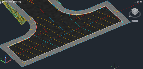
If roadside grading is required around the perimeter off the turning head, this can be added by extracting the corridor featureline for the back of footpath, and either adding this back into the corridor as a new baseline and applying grading, or else using a grading object to place grading on the featureline.
For AutoCAD Civil 3D training information, please visit our Training Courses page.

Author
Dave Bosworth
As a Civil Engineering Surveyor, Dave worked for many years on construction projects across the UK where he gained unique experiences in the use of design technology in both infrastructure engineering and GIS/mapping.


