First, there is the division between “Plans” and “Project Files”. This is contained in the document management module of BIM 360, that accompanies both BIM 360 Coordinate and BIM 360 Design.
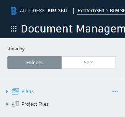
Fig 1. BIM 360 Default Sections
In the first instance, there are separate lists of supported file types for each section; In turn, each of the supported files types in the “Plans” section are treated very differently than if they were loaded into the “Project Files” section.
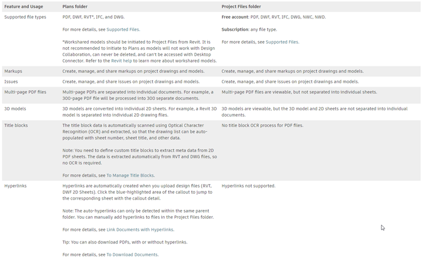
Fig 2. BIM 360 Help: Definition of Behaviours in “Plans” and “Project Files” Sections
To summarise the image above, multi-page PDFs, Revit models, DWG and DWF drawings are extracted into individual files in the “Plans” section but are displayed as single files in the “Project Files” section.
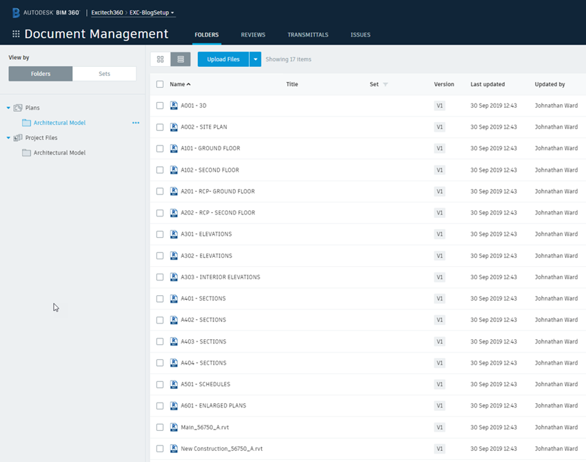
Fig 3. Model 56750_A.rvt Loaded to the “Plans” Section of BIM 360
Here, the model is saved into the “Plans” section and the individual views and sheets specified by the current “Publish Set” are extracted and displayed as though they were individual files.
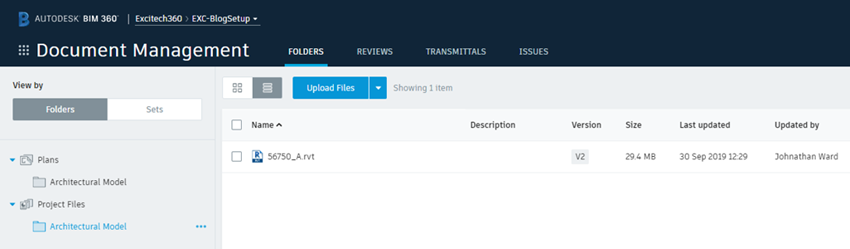
Fig 4. Model 56750_A.rvt Loaded to the “Project Files” Section of BIM 360
Now, the model is saved into the “Project Files” section, with the same current “Publish Set”, but here the model is displayed as a single file; the individual sheets and views being available when the file is selected for viewing.
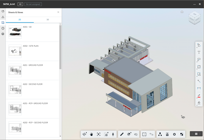
Fig 5. Model 56750_A.rvt Viewed from “Project Files” Section
The publish set is established from within the Revit model, located in the “Collaborate” tab on the ribbon.
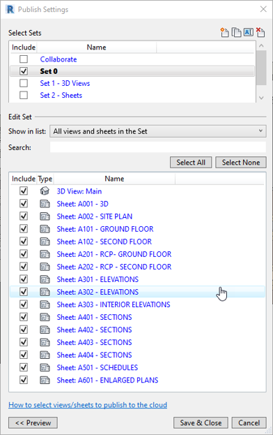
Fig 6. Model 56750_A.rvt Current Publish Set
The next division between the 2 sections is that BIM 360 Design stores its files in the “Project Files” section, whilst BIM 360 Coordinate uses the “Plans” section. There has been much consternation around this aspect of BIM 360, and specifically where both BIM 360 Design and BIM 360 Coordinate are being utilised on a project.
The ideal situation would be that Coordinate used the same files as those created by Design. All is not lost though, as it is possible to (semi) automate the process of creating our coordination models. In the process, we can also create a series of what in Navisworks terms would be called search sets. The process is straightforward and reasonably quick to set-up.
Create a new (blank) Revit model and create 3D views to match the categories that you would like BIM 360 Coordinate to automatically clash for you, using the standard visibility / graphics overrides, then save this model as a cloud model and select your desired coordination space in the “Plans” section.
Next, link the Revit models requiring clashing. I’ll go through the location of these models soon, but the final result should give you something like this in Revit.
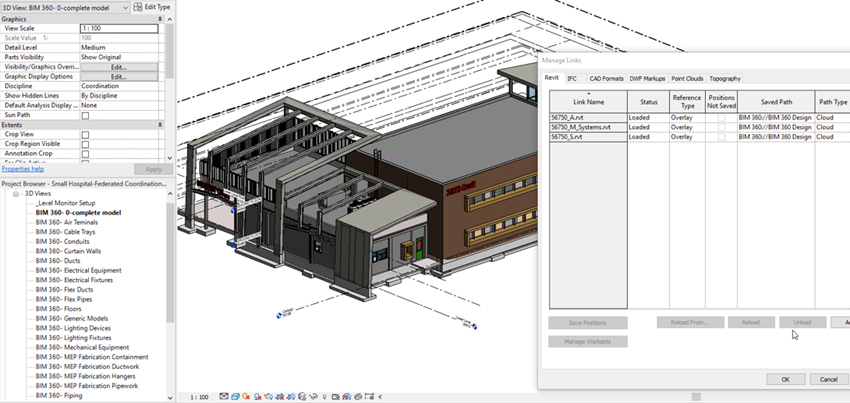
Fig 7. Federated Clash Model with “Search set” Views
Finally, use the Copy / Monitor tools to copy (and monitor) the levels from one of the linked models. I picked the Architectural model in this example.
The 3D views (prefixed with BIM360 in the example above) are added to a publish set in Revit, for extraction by BIM 360 Coordinate, saved and published.
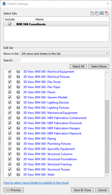
Fig 8. Federated Clash Model Publish Set
 Now for the location of the Revit models to link into the federated clash model.
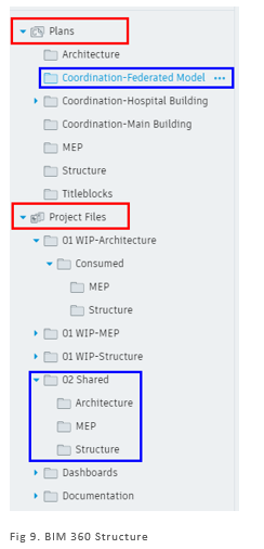
This part assumes that BIM 360 Design is also configured in the project, with the files stored in the “Project Files” section, as required. In Design, teams are created and assigned files, in this example;
- Architecture
- Structure
- MEP
The folders assigned to those teams are;
- 01 WIP-Architecture
- 02 WIP-MEP
- 02 WIP-Structure
As packages are created and shared with the design team, through BIM 360 Design, 2 things happen;
- packages are consumed by each team (into their respective “Consumed” folder), and
- copies of the shared models are copied into a shared location. This is created automatically by BIM 360 Design and called “Shared”, renamed in the example to “02 Shared”.
It is from here that the models are linked into the federated clash model.
When this model is saved (and the latest version published), the individual views are extracted by BIM 360.
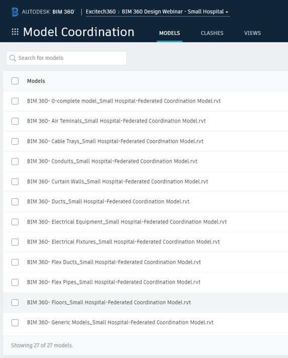
Fig 10. Model Coordination View of Federated Clash Model
Viewed in BIM 360 Coordinate, they will display the automatically generated clash matrix.
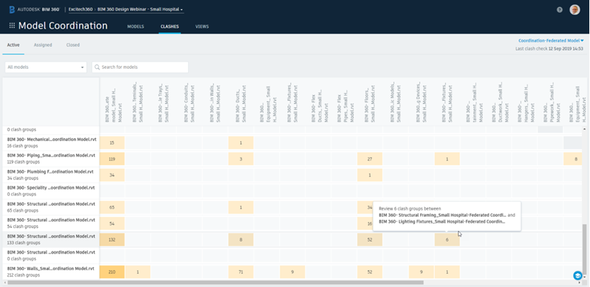
Fig 11. Clash Matrix from Federated Clash Model
If you would like more information on BIM 360 Coordinate, please visit our webpage: http//:www.Symetri.co.uk/Products/BIM-360-Coordinate

Author
Johnathan Ward
From a background in both the construction and manufacturing industries, Johnathan has gained a detailed working knowledge of both the processes and workflow methodologies employed in achieving the optimum operational performance.


