
Autodesk Civil 3D provides the necessary tools to create an alignment and, at the same time, to convey its geometrical information through labels and tables.
Within this blog, I'm going to focus on how Autodesk Civil 3D provides the necessary tools to create an alignment along with conveying its geometrical information through tables.
The following steps detail how to create a new customised style for a setting out table and how to use and apply that style to an existing alignment within Civil 3D.
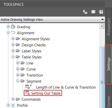
In the Toolspace palette, go to the Settings tab and expand Alignment --> Table Styles --> Segment. Create a copy of the Length of Line & Curve & Transition style from the UKIE template by right clicking on it and selecting Copy… as shown below.

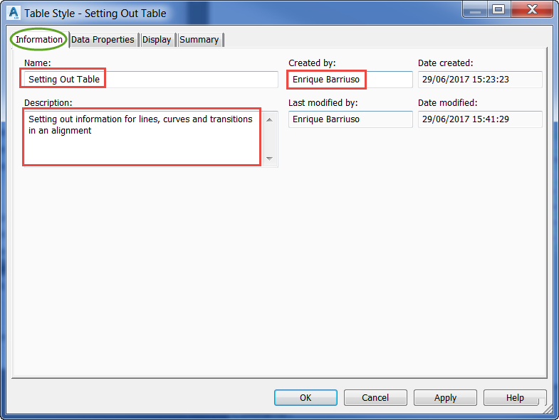
- The Table Style dialog window will pop up. In the Information tab, we can modify the Name, Description and Created by fields.
- Go to the Data Properties tab and customise the table adding, removing and reordering the columns provided in the style we started from. The process is the following:
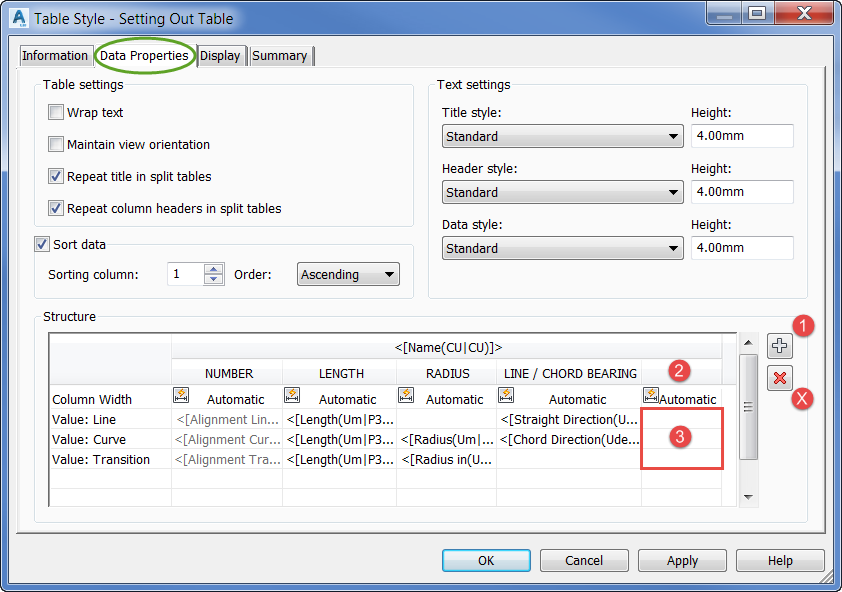
- To add a column, click on the plus sign on the right (1), double click on the column header (2) to give it a name and finally double click on each of the value fields (3).
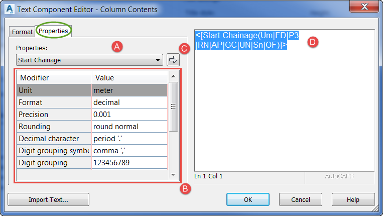
- For step (3), you will get a dialog like the one below. Just select a property from the list (A), change the modifiers (B) and don’t forget to click on the arrow (C) to populate the text field (D).
- To delete a column, select it by clicking on the header and then click on the red cross on the right (X).
- To reorder the columns, you can just click on the header and drag them to a new position.
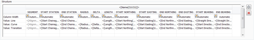
- In our example, we have configured the following structure for our table:
- Click OK to save your changes. The newly created style will be available in the Toolspace palette, on the Settings tab.
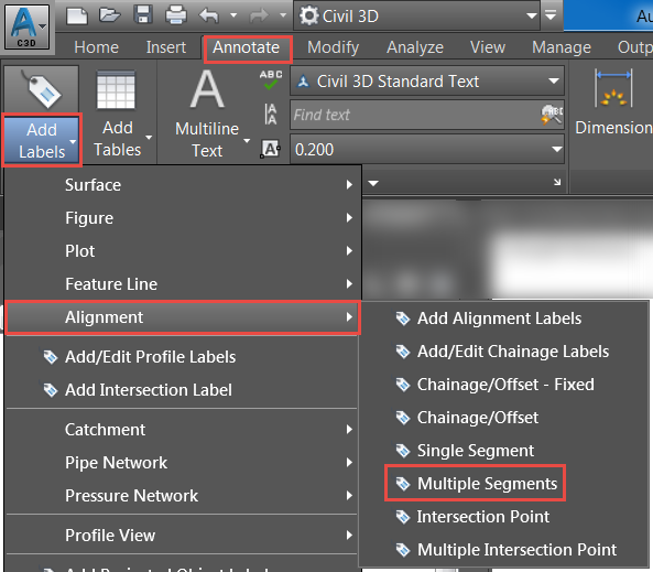
- Having completed the style for the table, we need to create some labels in the alignment to refer to. That can be achieved from the Annotate tab of the Ribbon, via Add Labels --> Alignment --> Multiple Segments. The contents of the labels don’t matter at this point as we are going to transform them into tags in the following step.

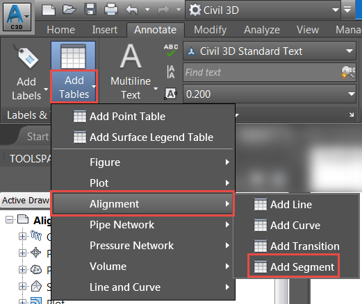
- In a similar way, we will now create the table from the Annotate tab of the Ribbon, through Add Tables --> Alignment --> Add Segment.
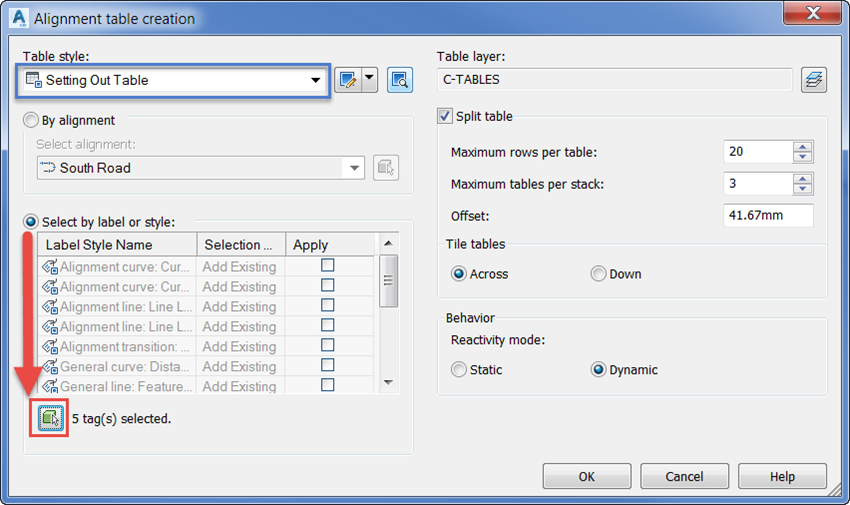
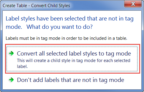
- In the Alignment table creation dialog box, select the style that we created and tick the Select by label or Style option. That will allow you to click on the icon on the bottom left corner and manually click on the labels from the previous step. After you select them you will get a prompt to convert all those labels to ‘tag mode’ that you will need to confirm.
- As a final step, it will ask you to pick a point to place the table in the drawing. The end result in our example is shown below. Note that the first column in the table refers to the tags that we created, marked with green circles.
For further information on Civil 3D, please check the product page here. This runs through all the features from the latest updates, along with instructional videos on how to perform certain tasks in Civil 3D.

Author
Enrique Barriuso
A qualified CEng MSpICE Civil Engineer with over 7+ years post graduate experience. Enrique graduated with a Master's in Civil Engineering, which covered a wide variety of subjects in the fields of transport, structural analysis, geotechnical design, coastal, water and environmental engineering. Enrique joined in 2015 and is an Autodesk Certified Professional in AutoCAD Civil 3D, subsequently helped many clients resolve their Civil 3D problems. He provides training in Civil 3D, AutoCAD and SketchUp.


